Electronics Engineer
Contact Me
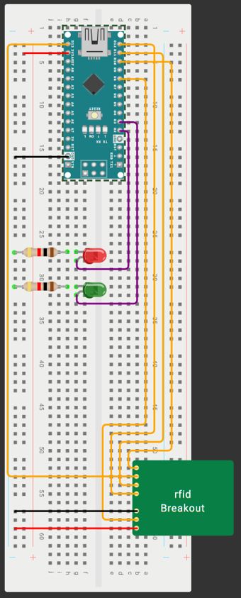
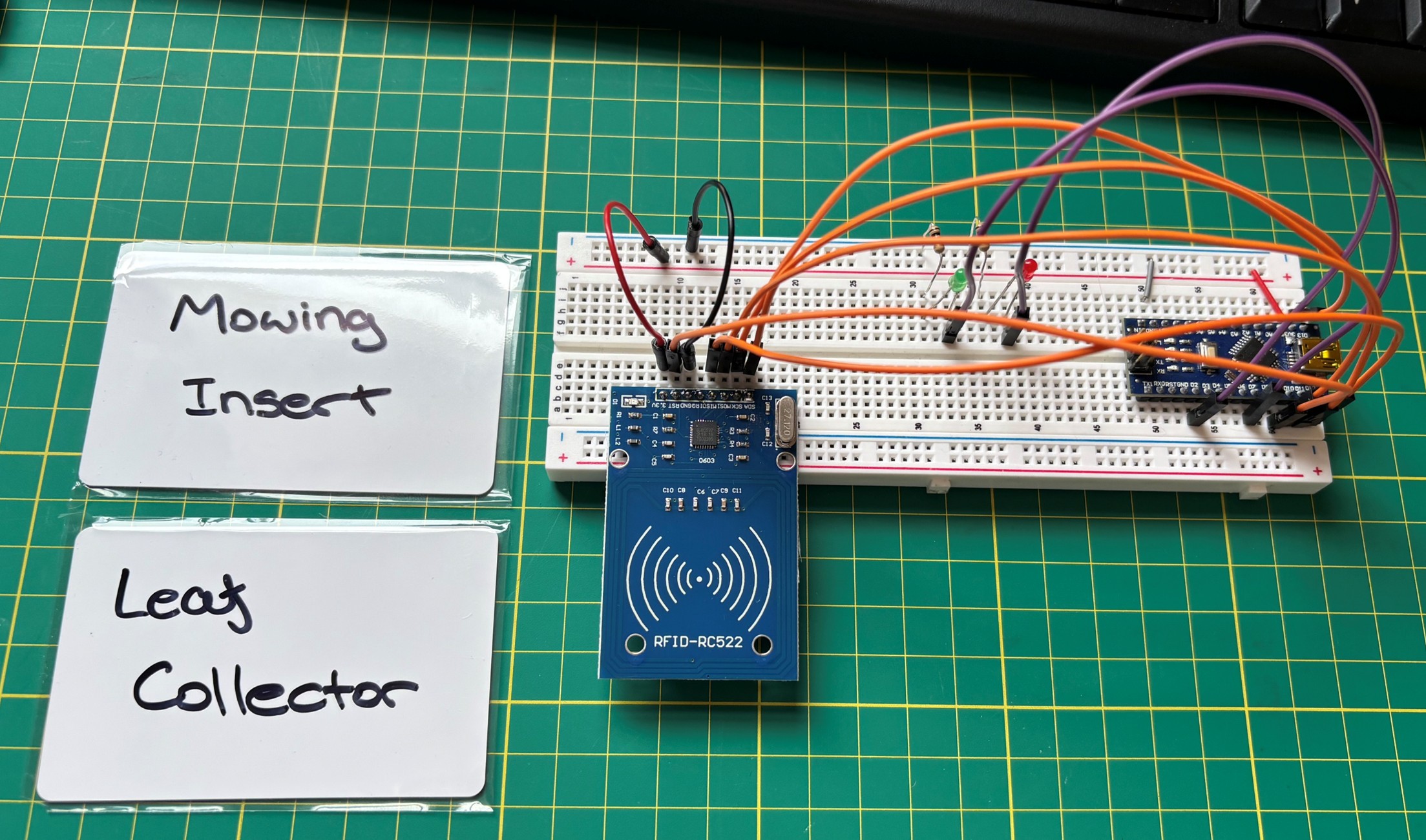
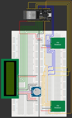
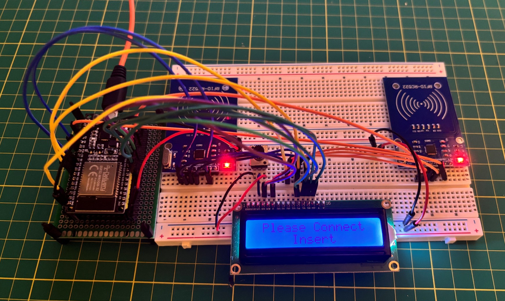
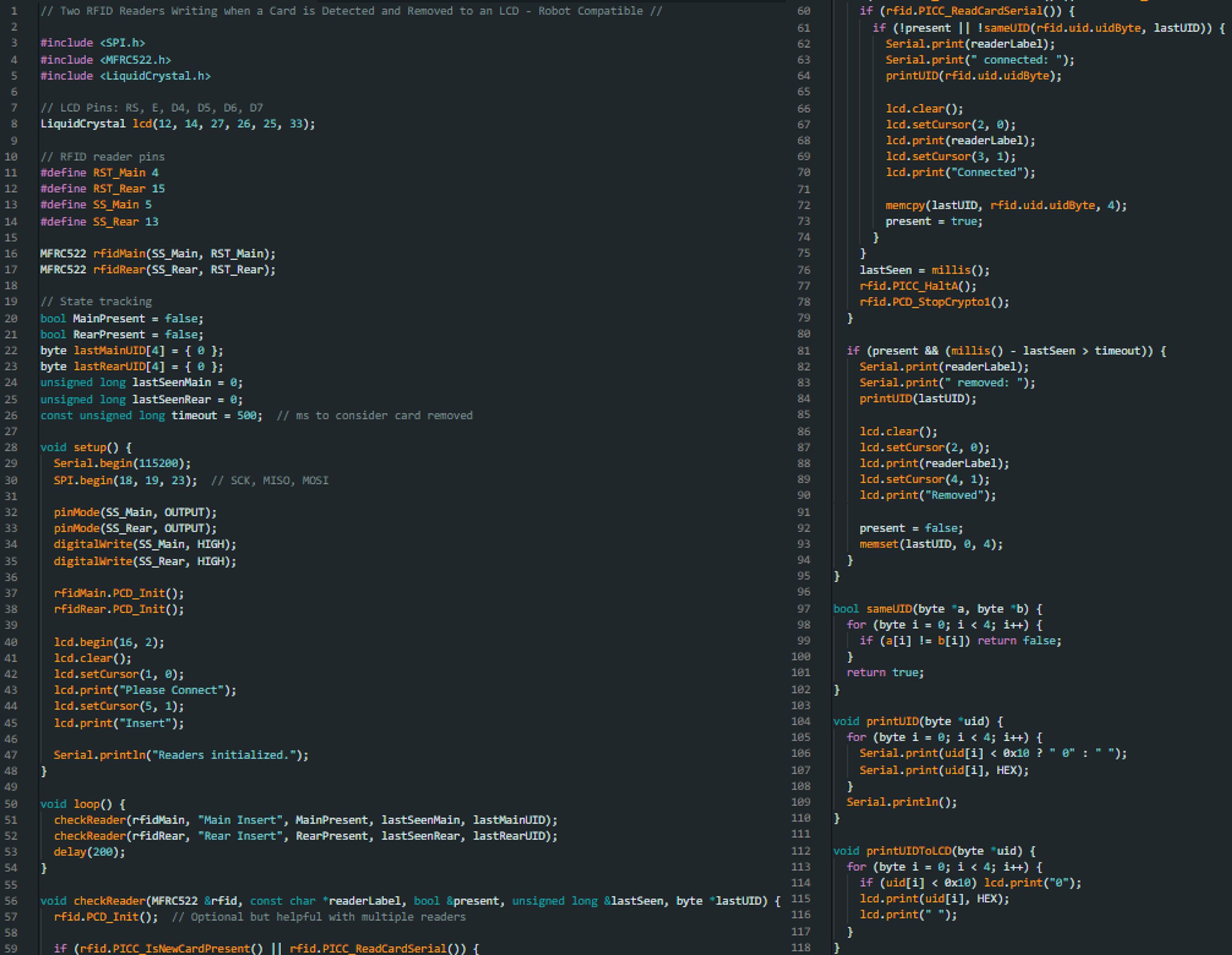
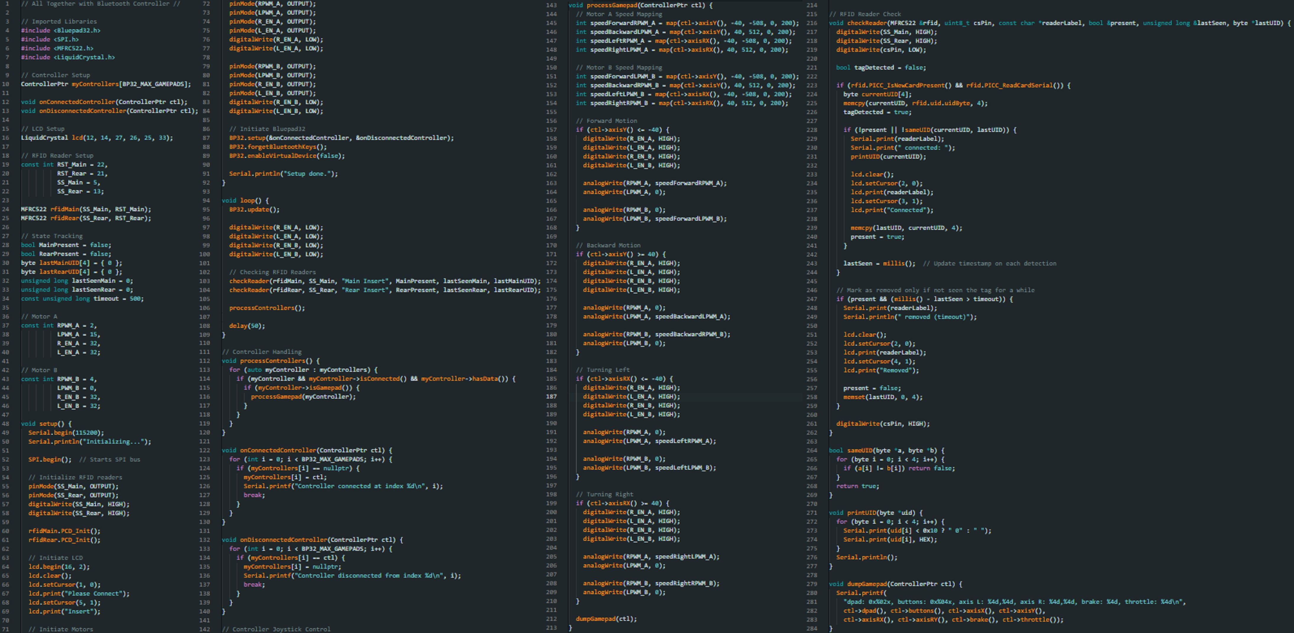
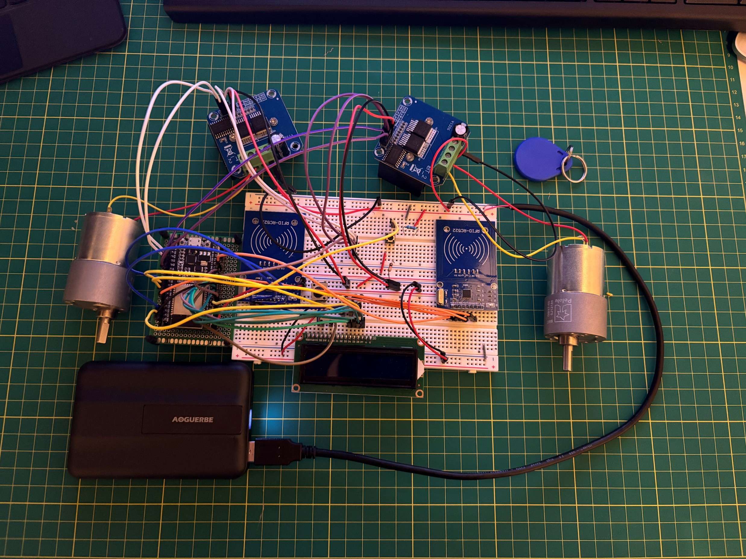
Initial stages of development for a modular autonomous garden care robot circuit. This circuit utilizes RFID scanners to detect when the different modules are inserted to the main body of the robot. The detection and connection of the modules is then displayed on the LCD.
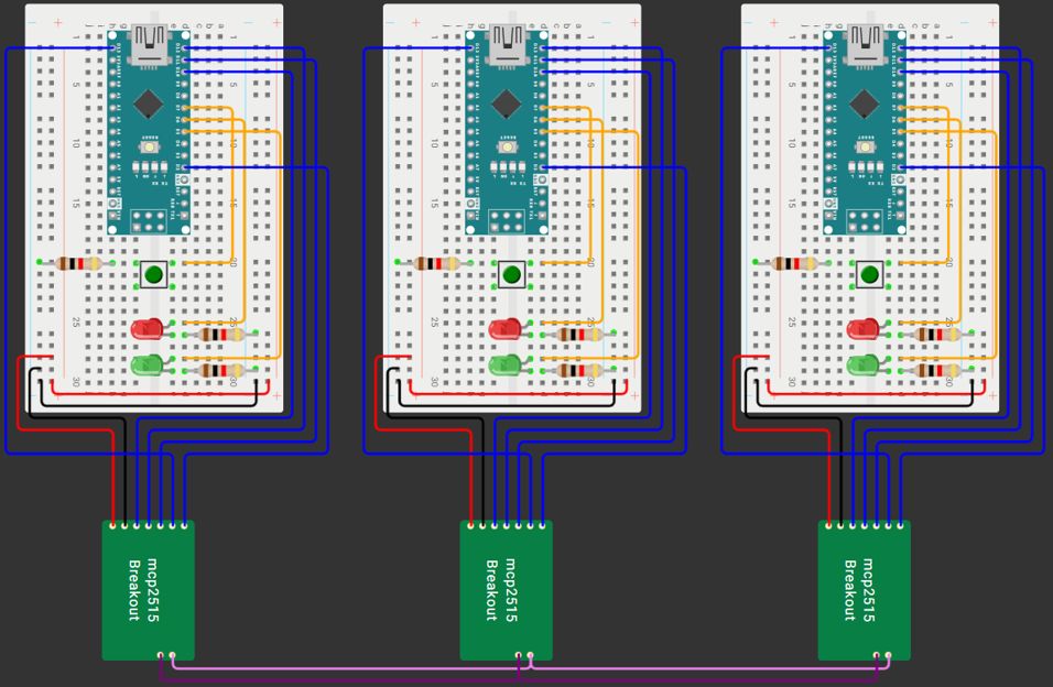
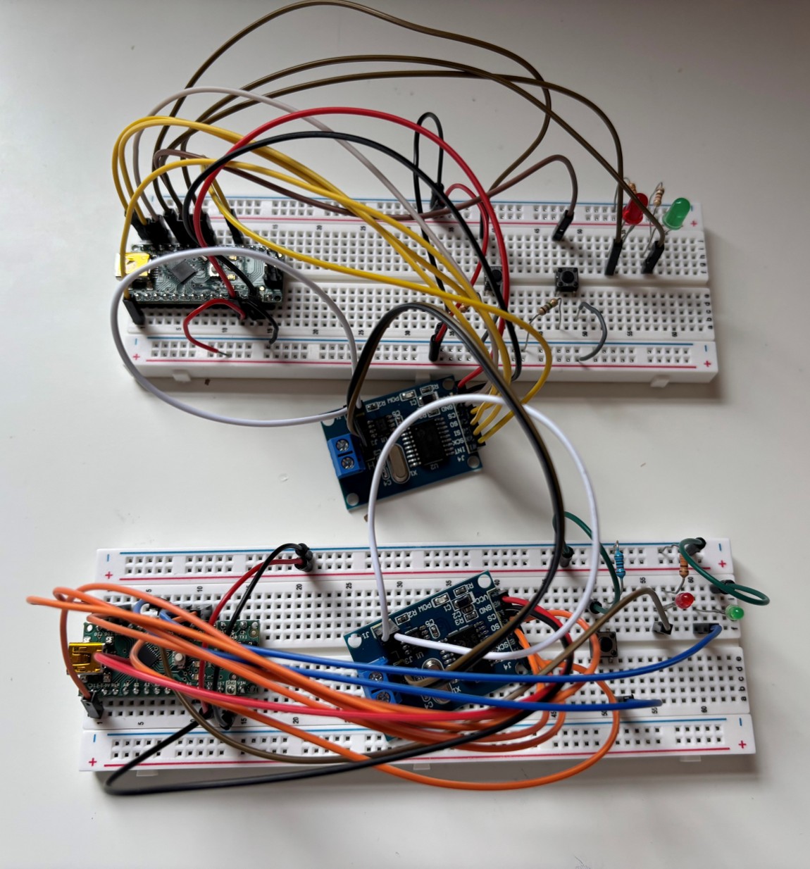
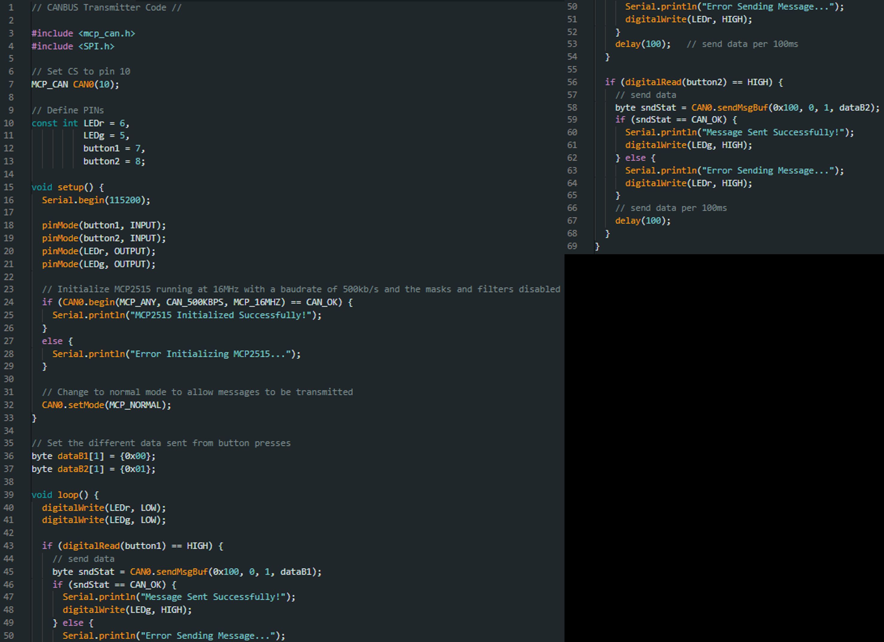
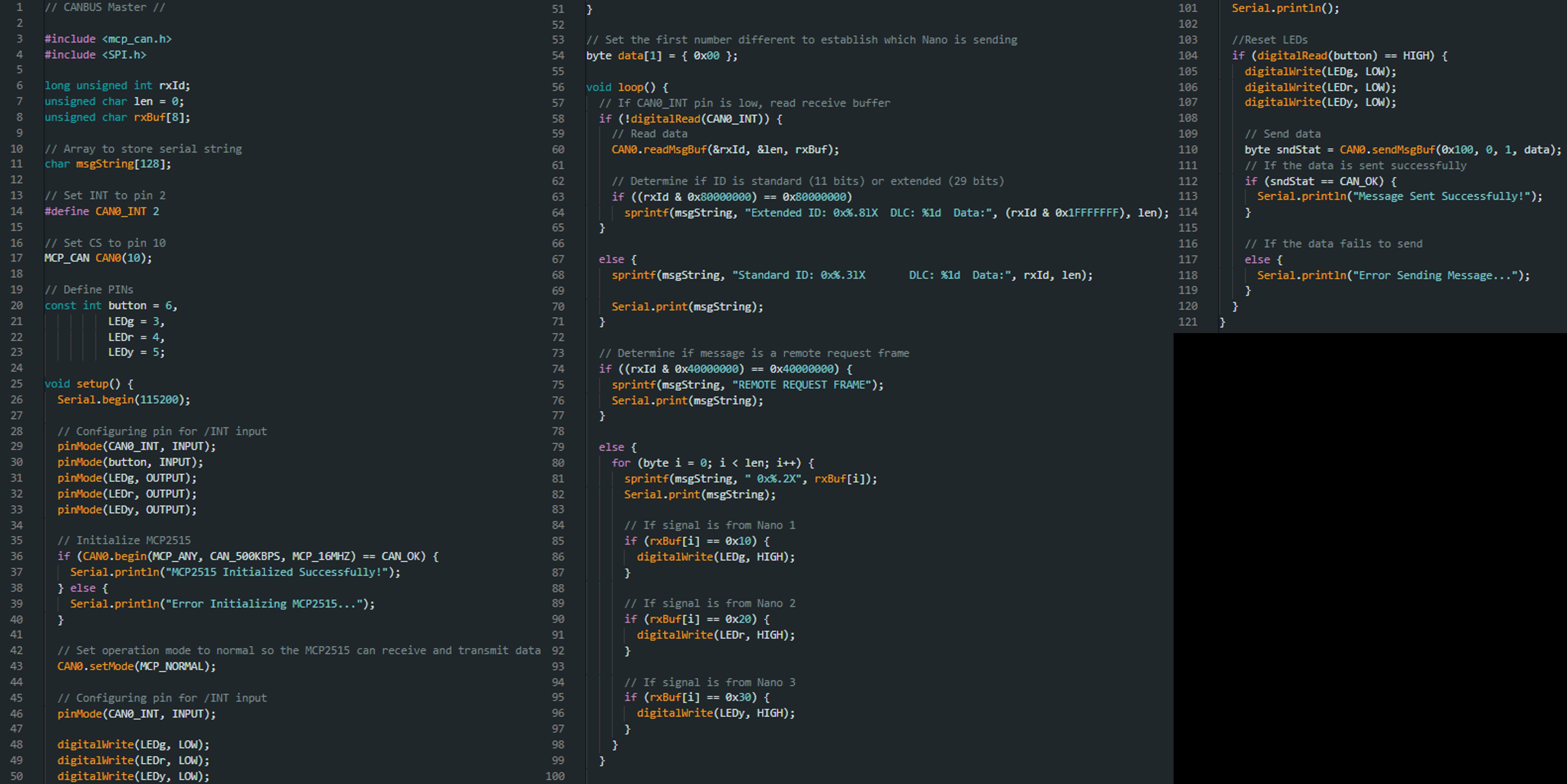
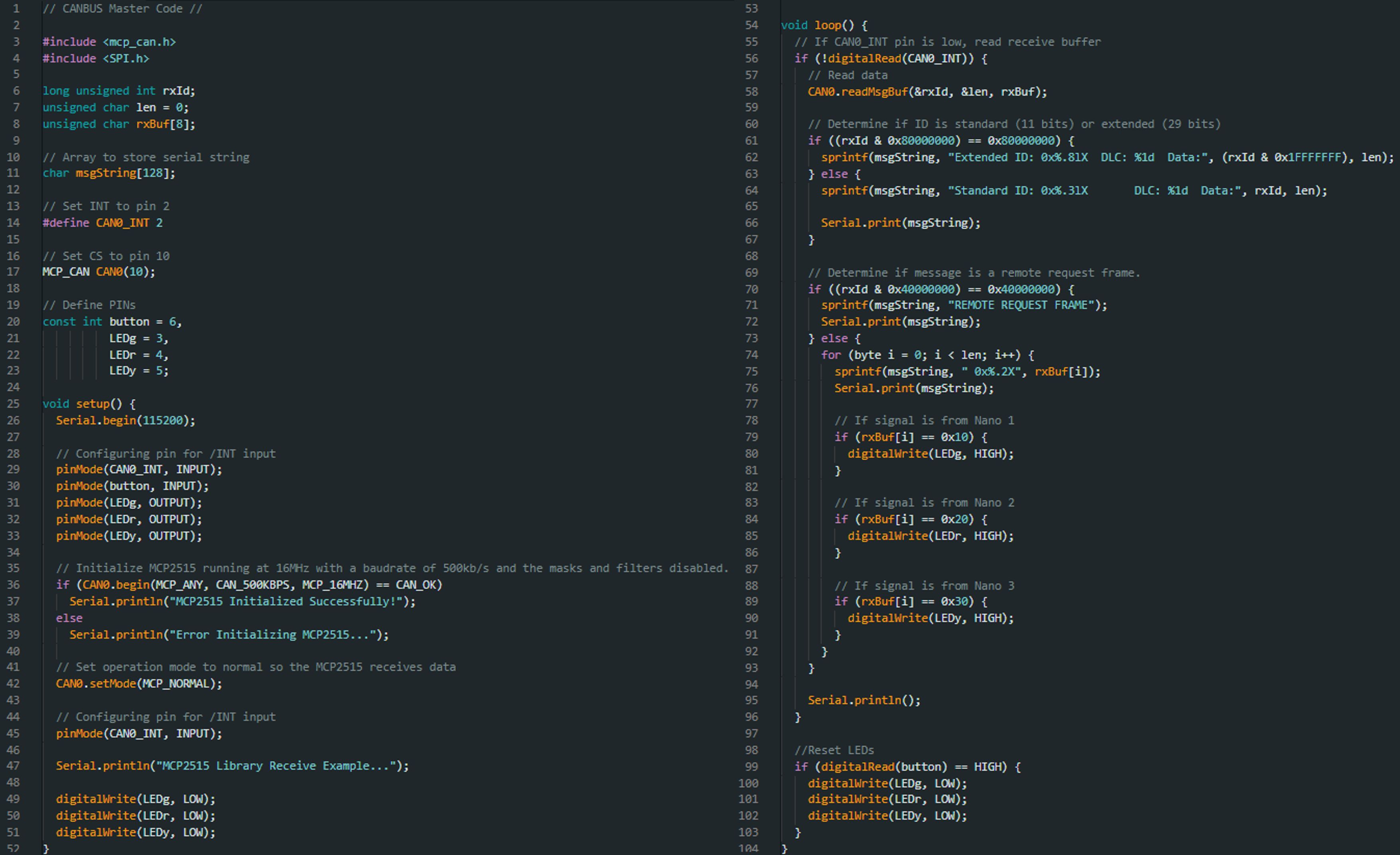
A circuit designed to test the limitations of basic connection and communication between different Arduino Nano's and ESP32 microcontrollers using the CANBUS connection protocol. This was used to determine the ease of set up and clarity of communication from the devices.
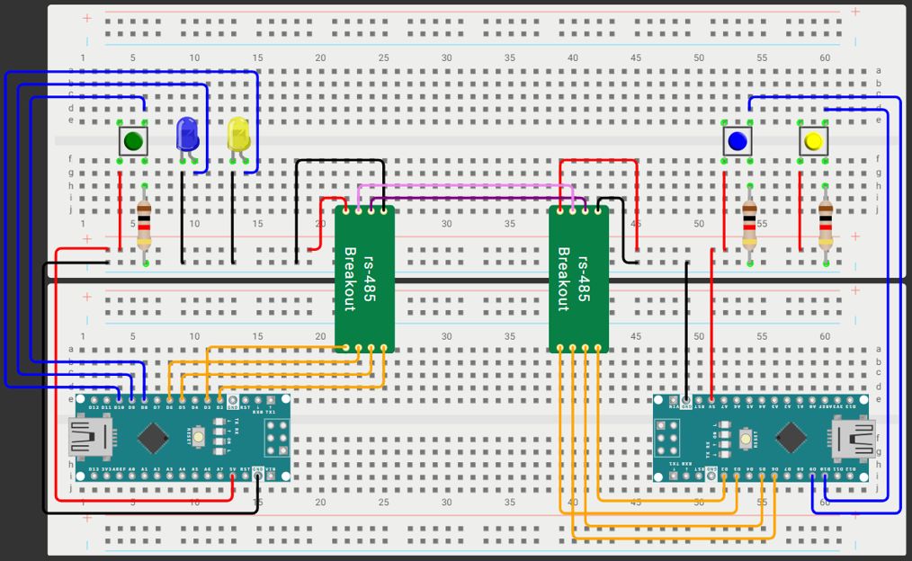
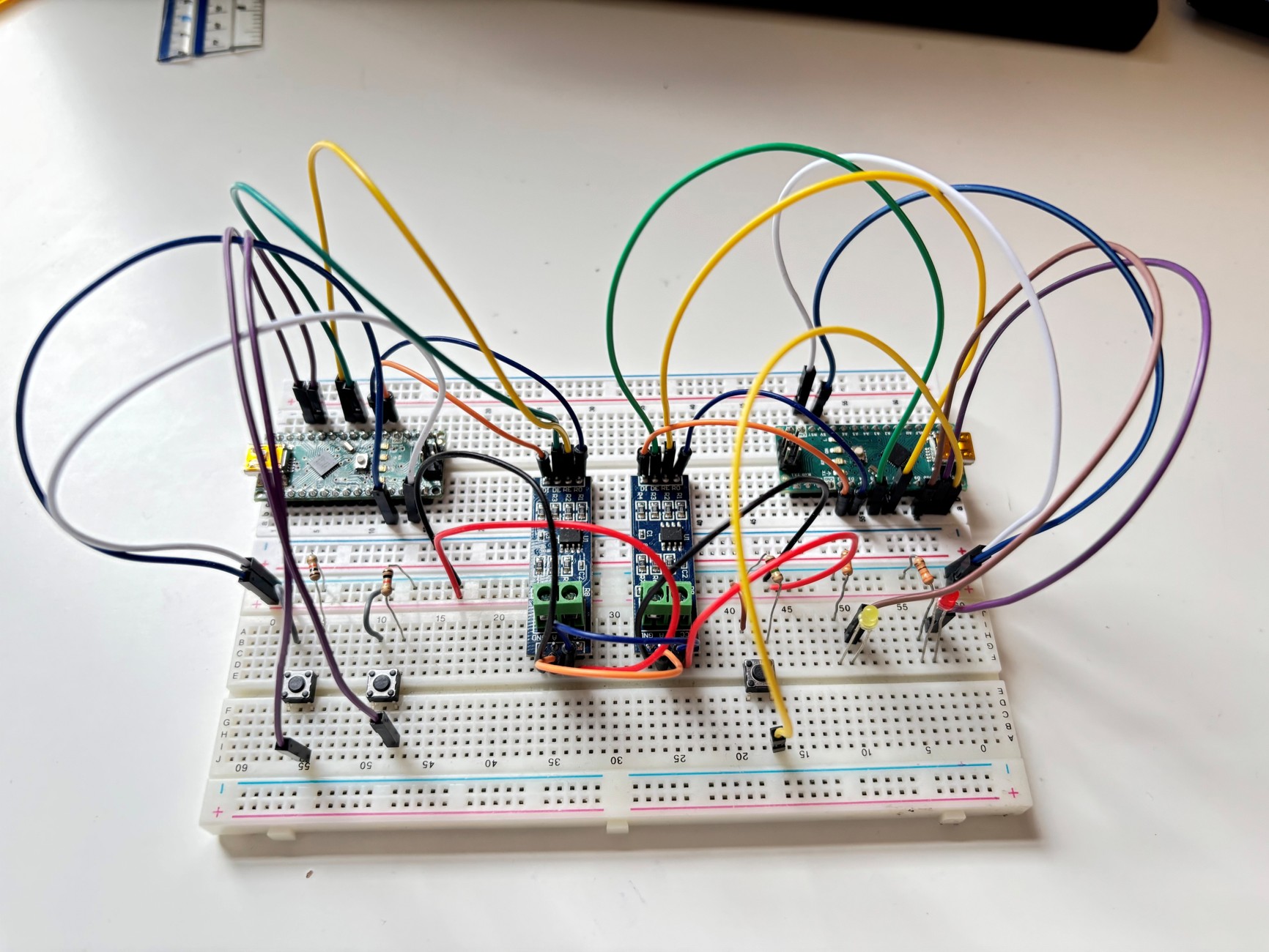
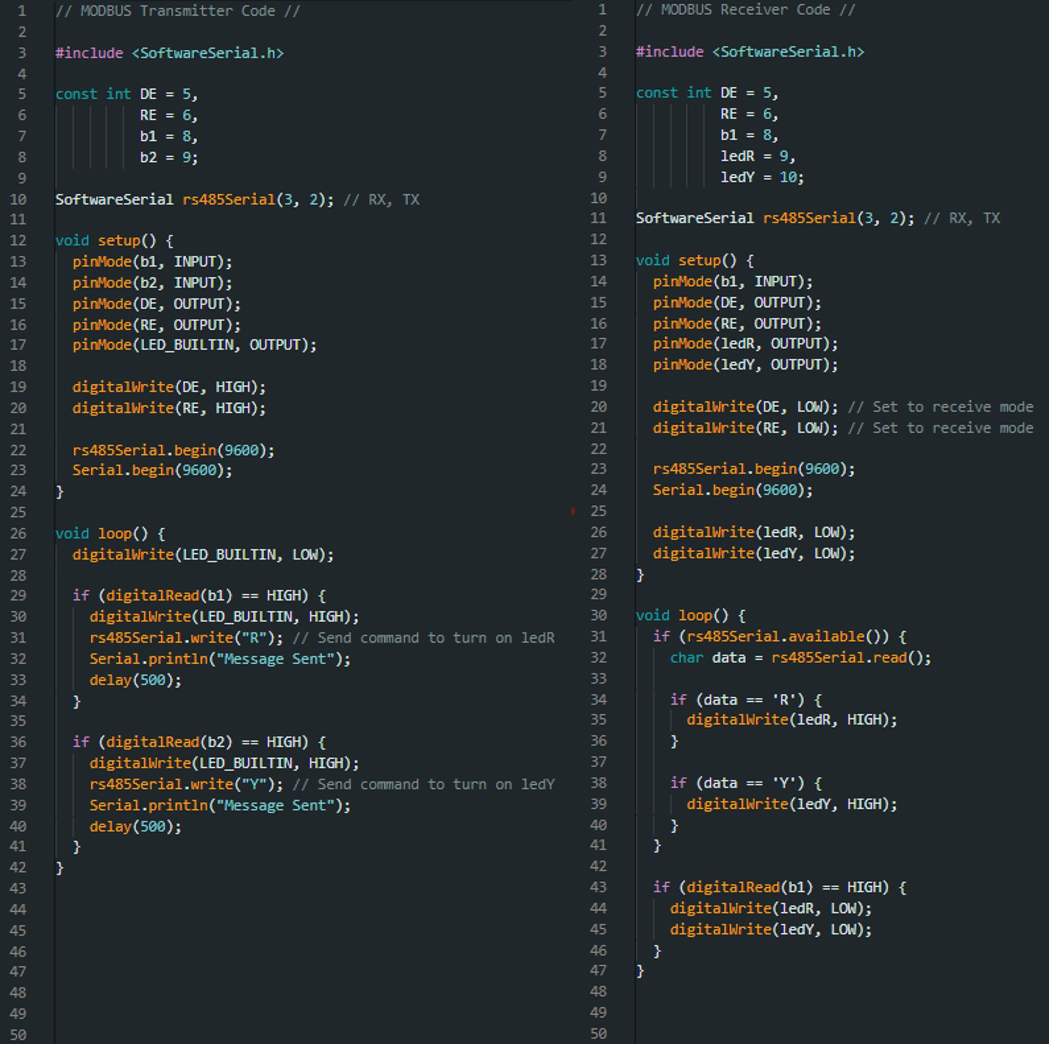
A circuit designed to test the limitations of basic connection and communication between different Arduino Nano's using the MODBUS connection protocol. This was used to determine the ease of set up and clarity of communication from the devices.
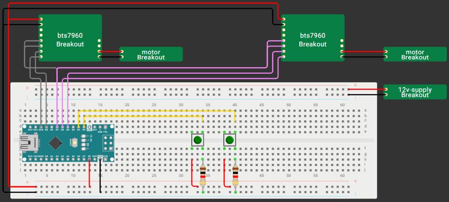
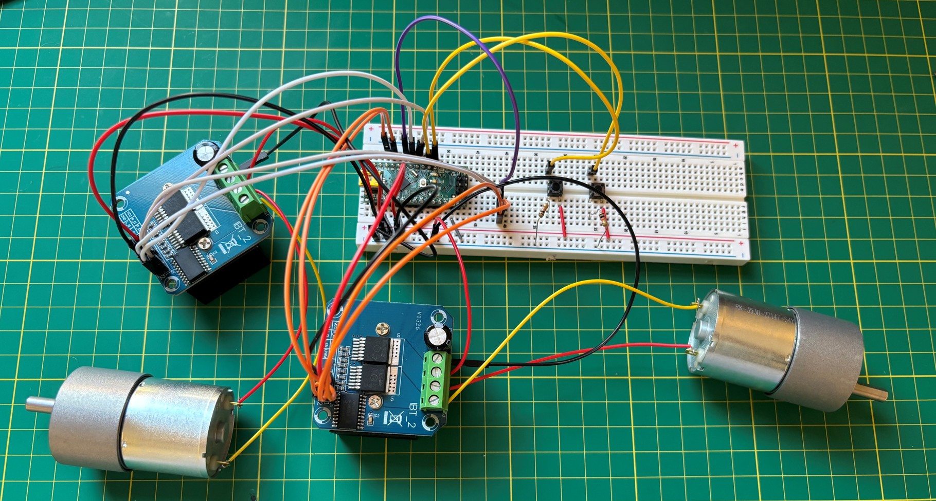
A small circuit to test a set of Pololu 50:1 37D 12V Metal Gearmotors with the BTS7960 motor controllers, and see whether they were compatible with each other for use on a bluetooth robot project.
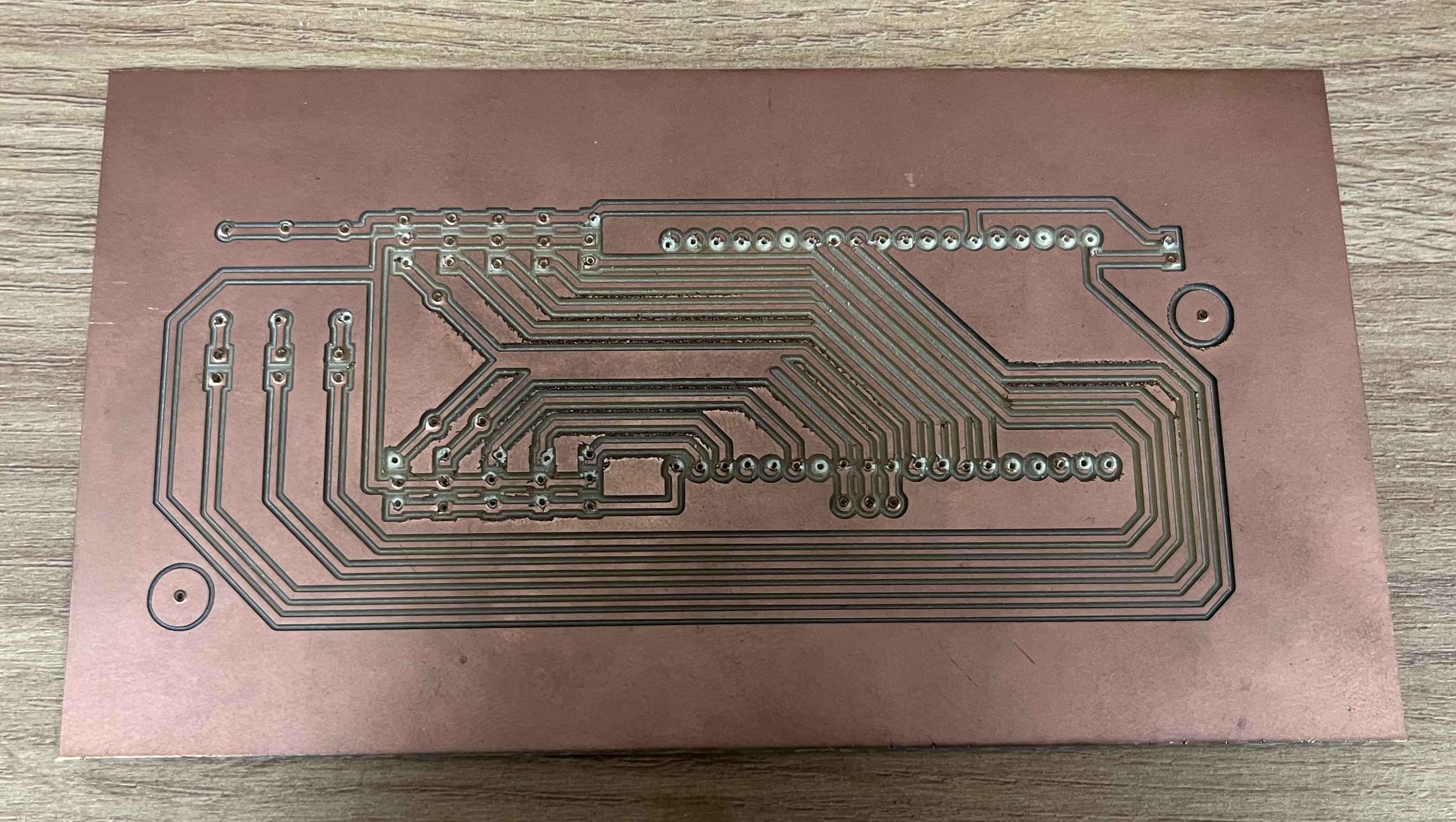
This PCB schematic and layout is for a robotic mower docking tracker, designed and built in Altium, that I built to assist with product benchmark testing while working for Bosch in their Lawn & Garden division. Attached to the PCB is an Arduino Nano that runs the circuit, an Ultrasonic Sensor (USS) that detects when the robot moves into a defined range, a Real Time Clock (RTC) that notes the exact date and time stamp when the robot either enters or leaves the defined range, a Liquid Crystal Display (LCD) to portray the latest docking/undocking, and an SD Card reader to save all the data collected onto an SD card for later analysis with either other robots or local meteorlogical data.
Before a PCB was designed for the project above I first created a prototype to test whether the device would work. For this I soldered all the components onto two layers of Perforated Board, and used a combination of the metal tracks built into the board and other small wires soldered on to create the working circuit.
The final test circuit built for a bluetooth controlled robot that utilises a PS4 controller that connects via bluetooth to a ESP32 microcontroller. From this one can use the two joysticks on the PS4 controller to controll the speed and direction the two motors rotoate, therefore driving the roboteither forwards or backwards, or turning it.
One project at University was to design and build a small bluetooth controlled robot that could you could navigate around a complex course that involved: A bridge with a tunnel underneath the robot had to fit through, a sea saw the robot had to drive over, and an uneven road the robot had to scale. Around the course there were also a series of tea lights placed at different heights the robot needed to extinguish. This robot utilised the rocker boogie suspension, similar to the suspension used by the Mars rover, along with tank treads for grip and support. Then for the extingsuishing system the rorobt has an extendable arm, and a tube that carried air from a small PC fan. The arm allowed the robot to reach different heights with ease, as well as reach over any wall or obstacle in the way of the tea light.